
Flow Visualization with CorVue |
|
Boundary Interaction in Stratified Crossflow |
|
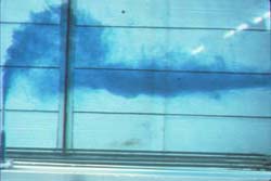
Ambient density stratification can cause
boundary interaction as shown here by a buoyant
jet trapping and density current formation in
density stratified crossflow.
|
A CorVue visualization of flow class S1
trapping by a density-stratified crossflow followed
by density current far-field
mixing. Enhanced image has ambient boundaries, and flow module regions
with RMZ and TDZ locations highlighted.
|
Boundary Interaction in Stratified Ambients with Upstream Density Currents |
|
l.jpg)
This experiment shows ambient density stratification causes near-field flow trapping and subsequent density current formation for a single port discharge in a stagnant ambient.
|
CorVue S5 flow classification visualization shows a near-field flow trapped by stratified crossflow, buoyant density current upstream spreading, and subsequent far-field mixing (enhanced image).
|
Upstream Density Currents |
|
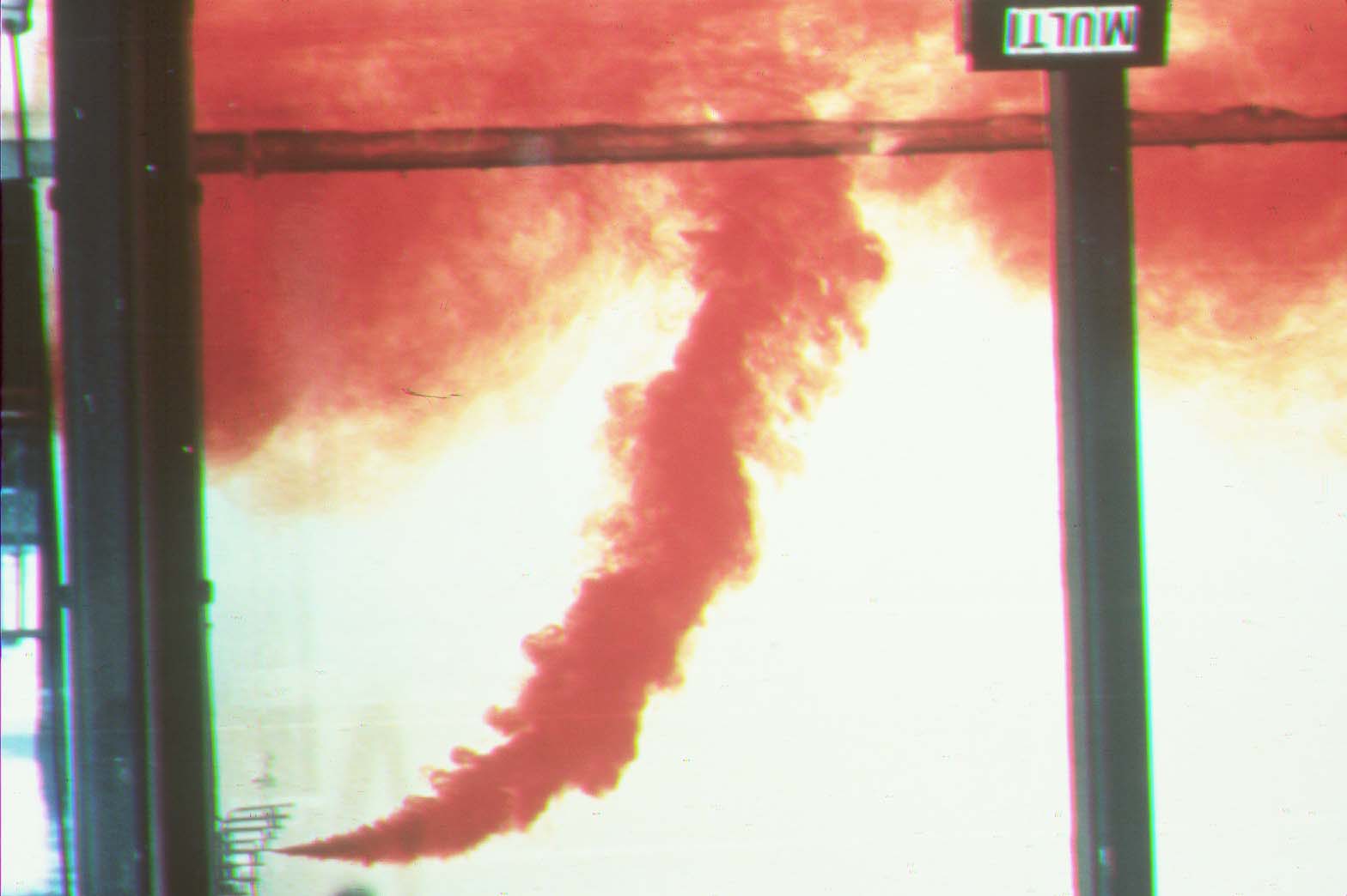
One nozzle is dyed in this experiment with a multiport diffuser (Photo: G. Jirka). Note the formation of a hydraulic jump after surface contact.
|
A CorVue 3-D visualization of a unidirectional multiport MU1V flow classification showing water surface boundary interaction in the near-field, surface density current upstream intrusion and stagnation point (Enhanced image).
|
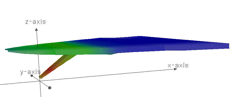
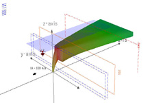
Near-field and Far-field Flow Visualizations of Density Currents and Mixing Zones |
|
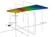
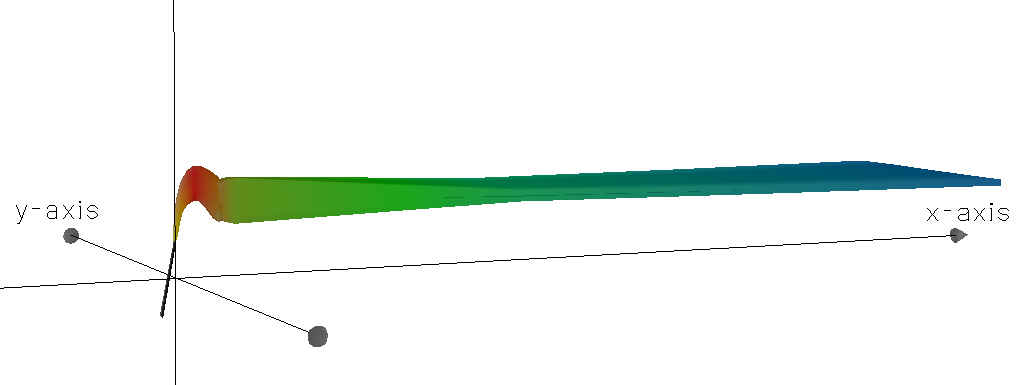
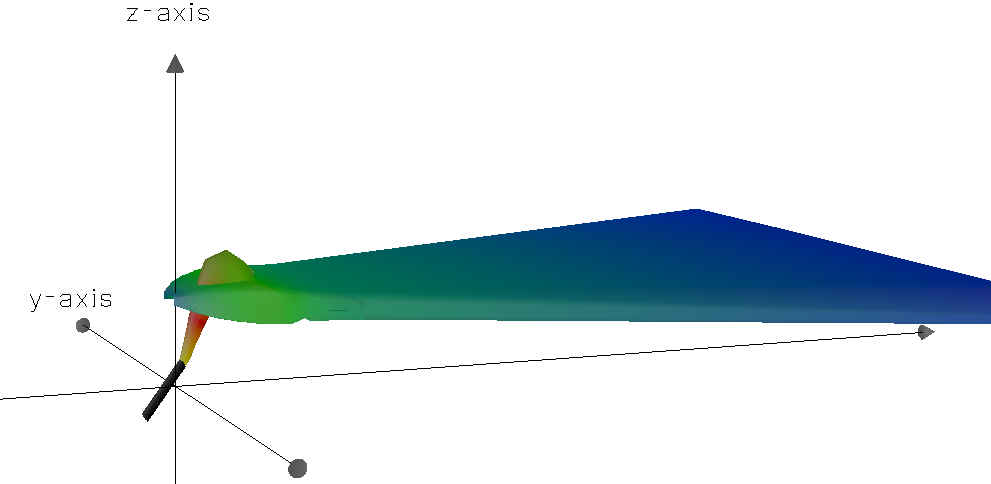
A CorVue 3-D view of CORMIX1 flow class V5 flow mixing zone locations for regulatory TDZ and RMZ values for a CORMIX1 simulation of flow class V5 (larger image).
|
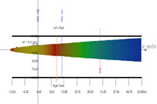
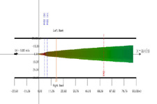
Corresponding CorVue plan (top) view of TDZ and RMZ locations for a CORMIX1 simulation of flow class V5 (larger image).
|
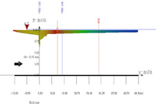
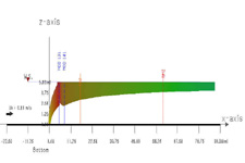
Corresponding CorVue side view of TDZ and RMZ locations for a CORMIX1 simulation of flow class V5 (larger image).
|
|
Predicted Plume Centreline Concentration and Dilution Plots |
|
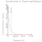
CorVue maximum concentration vs. downstream distance (larger image).
|
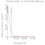
CorVue maximum concentration vs. centerline distance (larger image).
|
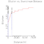
CorVue minimum dilution vs. downstream distance (larger image).
|
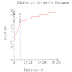
CorVue minimum dilution vs. centerline distance (larger image).
|
Near-field and Far-field Regulatory Mixing Zone Visualizations for Stable Flows |
|
A CorVue 3-D view of TDZ and RMZ locations for a CORMIX1 simulation of flow class V2 (larger image).
|
Corresponding CorVue side view of TDZ and RMZ locations for a CORMIX1 simulation of flow class V2 (larger image).
|
Corresponding CorVue plan (top) view of TDZ and RMZ locations for a CORMIX1 simulation of flow class V2 (larger image).
|
|